
PCB Current Capacity Calculator
Revisit an existing board rule with Circuit Edge: compare the routed width and copper specification against a revised load.
Design inputs
01 / CONFIGURECalculation workspace
02 / EXPLORECapacity describes an isolated empirical baseline, not a current rating or a fuse trip current. Results are estimates; confirm critical designs with your fabricator.
How it works · formula & assumptions
I = k × ΔT^0.44 × (w_mil × t_mil)^0.725.
Capacity describes an isolated empirical baseline, not a current rating or a fuse trip current.
Can the existing route support the revised load?
Can the existing route support the revised load?
A component change can raise current without changing the board outline. Use the narrowest routed width and minimum finished copper to screen the updated path, then compare the result with the component and connector limits.
Make the design change review reproducible
For a Circuit Edge review, attach the board revision, net name, minimum width and revised continuous load. Record fault protection separately. A numerical current estimate does not explain whether an upstream fuse will clear before a local conductor is damaged.
The question this Circuit Edge workspace addresses
Revisit an existing board rule with Circuit Edge: compare the routed width and copper specification against a revised load. Capacity describes an isolated empirical baseline, not a current rating or a fuse trip current.
Formula and assumptions
I = k × ΔT^0.44 × (w_mil × t_mil)^0.725.
Start from finished copper geometry
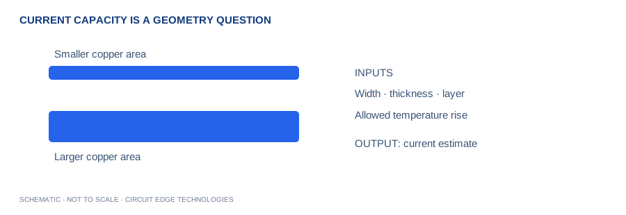
This reverse calculation takes an existing width and asks which continuous current corresponds to the chosen rise in the empirical model. Use the routed width at the tightest sustained section, not the average width of a large pour. Confirm whether the board quote describes base copper or finished copper. Small differences in thickness affect cross-sectional area and therefore the estimate; a measured sample or fabricator minimum gives a more defensible starting input.
Do not confuse capacity with protection
A calculated current is not an overload-protection setting. A fuse or circuit breaker has its own time-current behavior, and a PCB conductor can be damaged during a fault before that protection clears. Evaluate the prospective short-circuit current, supply impedance and protective device separately. Connectors, relays, solder joints and components may also limit the assembly current below the copper screening value shown here.
Compare layers intentionally
The legacy formula uses different coefficients for internal and external conductors. Changing the layer selector therefore changes the estimate even when width and copper weight stay fixed. Real boards also conduct heat into adjacent planes and dielectric. Do not infer that every internal trace always runs hotter than every external trace. If the difference changes a design decision, evaluate the actual construction using measurements or a more detailed thermal model.
Turn the estimate into a design rule
Choose an operating current below the screening result with a project-specific allowance for uncertainty. Check manufacturing minimum width and etch tolerance. If multiple traces or layers share current, confirm where they join and whether resistance will distribute the current evenly. The trace-width companion tool can invert this result to confirm consistency. Release the selected width, copper requirement and validation evidence together so reviewers can reproduce the decision.
Work from your project brief
Start by confirming the units shown beside each input. Enter the operating condition you expect in the finished product, then change one variable at a time so the effect stays clear. The plus and minus controls make small adjustments, while the slider is useful for a quick sensitivity sweep. Blank fields, impossible ranges and unsupported geometries stop the calculation instead of silently preserving a previous result. A unit change converts the displayed value while the underlying calculation keeps a consistent canonical unit system.
Keep a Circuit Edge board-review record
Use Copy Results for a design-review note, CSV for a calculation register, and Share Link to preserve the input values in the URL. Download PDF creates a local report with the inputs, outputs, formula and limitations. The exported estimate is only useful when its assumptions remain attached. Keep the board revision, stackup revision, supplier tolerances and applicable load or interface requirement in the same review record. A later fabrication change can invalidate an earlier calculation even if the calculator inputs have not changed.
Separate the displayed digits from project confidence
Several digits are displayed to make comparisons and unit conversions useful. Those digits do not imply matching physical accuracy. Manufacturing variation, environmental conditions and the simplicity of the selected model can dominate the final result. Round the chosen design requirement in a direction that preserves engineering margin, then agree the tolerance with your fabricator. Use prototype measurements and the relevant analysis tools when a small change would affect reliability, regulatory compliance or product performance.
Worked example
A 0.301 mm external trace with 1 oz copper and a 10 °C rise screens at approximately 1 A. Use the defaults as a reproducible starting point, then substitute your own board data. When comparing a manual calculation, keep dimensional units consistent and avoid rounding intermediate values. If your result differs, check the input definitions before changing the model or applying an unexplained correction factor.
Continue with our calculation methodology, fabrication review checklist and high-speed layout guide. For board-specific support, contact Circuit Edge Technologies.
Frequently asked questions
What does the current capacity tool calculate?
Revisit an existing board rule with Circuit Edge: compare the routed width and copper specification against a revised load. Capacity describes an isolated empirical baseline, not a current rating or a fuse trip current.
Which formula does this calculator use?
I = k × ΔT^0.44 × (w_mil × t_mil)^0.725. The Methodology page records the model and its limitations so that a design reviewer can reproduce the assumptions.
How should I check the input definitions?
This reverse calculation takes an existing width and asks which continuous current corresponds to the chosen rise in the empirical model. Use the routed width at the tightest sustained section, not the average width of a large pour. Confirm whether the board quote describes base copper or finished copper. Small differences in thickness affect cross-sectional area and therefore the estimate; a measured sample or fabricator minimum gives a more defensible starting input.
What is a useful worked example?
A 0.301 mm external trace with 1 oz copper and a 10 °C rise screens at approximately 1 A. This example is a starting point for checking units, not a universal production recommendation.
Can I use the result as a fabrication or compliance approval?
Capacity describes an isolated empirical baseline, not a current rating or a fuse trip current. Obtain the required engineering and manufacturing review before releasing a critical design.
How can I save and share my calculation?
Copy Results includes the inputs, outputs and limitations. CSV provides a local record, while Download PDF creates a local engineering report. Share Link encodes the canonical input values in the URL. Anyone with the link can reproduce that input set.
What should I verify before design release?
Choose an operating current below the screening result with a project-specific allowance for uncertainty. Check manufacturing minimum width and etch tolerance. If multiple traces or layers share current, confirm where they join and whether resistance will distribute the current evenly. The trace-width companion tool can invert this result to confirm consistency. Release the selected width, copper requirement and validation evidence together so reviewers can reproduce the decision.
Inputs and related calculators
Trace width, Temperature rise, Copper weight, Copper layer.