
PCB Impedance Calculator
Bring a proposed stackup to the Circuit Edge design desk and examine how its width and reference spacing affect the estimate.
Design inputs
01 / CONFIGURECalculation workspace
02 / EXPLOREEstimate only. Simple closed-form formulas omit solder mask, trapezoidal etching, copper roughness, frequency dispersion and nearby conductors. Symmetric stripline only; h is the copper-surface distance to either plane. Results are estimates; confirm critical designs with your fabricator.
How it works · formula & assumptions
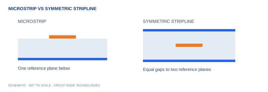
Microstrip Z0 = 87/√(εr+1.41) × ln[5.98h/(0.8w+t)]. Symmetric stripline Z0 = 60/√εr × ln[1.9b/(0.8w+t)], b = 2h+t.
Estimate only. Simple closed-form formulas omit solder mask, trapezoidal etching, copper roughness, frequency dispersion and nearby conductors. Symmetric stripline only; h is the copper-surface distance to either plane.
Which stackup will the supplier actually press?
Which stackup will the supplier actually press?
An impedance target becomes meaningful only when a conductor has a defined reference, dielectric construction and finished shape. Ask for a supplier-approved stack before locking width rules for a fast interface.
Connect the estimate to a controlled fabrication note
The Circuit Edge release should contain the target impedance, approved layer construction, agreed finished widths and the coupon or verification requirement. A change in prepreg thickness, mask or foil can require a new review even if the schematic is unchanged.
The question this Circuit Edge workspace addresses
Bring a proposed stackup to the Circuit Edge design desk and examine how its width and reference spacing affect the estimate. Estimate only. Simple closed-form formulas omit solder mask, trapezoidal etching, copper roughness, frequency dispersion and nearby conductors. Symmetric stripline only; h is the copper-surface distance to either plane.
Formula and assumptions
Microstrip Z0 = 87/√(εr+1.41) × ln[5.98h/(0.8w+t)]. Symmetric stripline Z0 = 60/√εr × ln[1.9b/(0.8w+t)], b = 2h+t.
Define the stackup before the trace
Impedance is a property of the conductor and its surrounding electromagnetic geometry. A width without a reference-plane distance is not enough. For microstrip, h is the dielectric distance from the conductor underside to the reference plane. For this symmetric stripline approximation, h is the equal surface-to-plane spacing on each side, so the plane separation is twice h plus copper thickness. Asymmetric constructions require a different model.
Use material data at the relevant frequency
An FR4 label does not specify one universal dielectric constant. Resin content, glass style, test method and frequency influence the effective value used by a solver. Ask for the actual laminate and prepreg construction and the fabricator impedance model. A Rogers or flex material likewise needs its own construction data. Do not substitute a marketing dielectric value without checking whether it matches the fabrication stackup and operating frequency.
Understand approximation boundaries
The logarithmic expressions describe simple uniform cross-sections. Extremely wide or thick conductors and unusual geometries can fall outside useful model behavior. The interface rejects some clearly unsuitable ratios instead of presenting a misleading negative impedance. Even a plausible positive answer does not prove model accuracy. Solder mask, etch taper, copper roughness, neighboring traces and finite planes can materially change the fabricated impedance.
Close the loop with manufacturing
Use this workspace to explore direction and sensitivity: wider traces generally lower impedance, while a more distant plane generally raises it. Then send a target impedance and tolerance to the board supplier and agree on the final width and coupon strategy. Review reference-plane continuity and transitions independently; a uniform-line estimate cannot certify an entire channel. Read the existing microstrip article for layout context and include an impedance report with the release package.
Work from your project brief
Start by confirming the units shown beside each input. Enter the operating condition you expect in the finished product, then change one variable at a time so the effect stays clear. The plus and minus controls make small adjustments, while the slider is useful for a quick sensitivity sweep. Blank fields, impossible ranges and unsupported geometries stop the calculation instead of silently preserving a previous result. A unit change converts the displayed value while the underlying calculation keeps a consistent canonical unit system.
Keep a Circuit Edge board-review record
Use Copy Results for a design-review note, CSV for a calculation register, and Share Link to preserve the input values in the URL. Download PDF creates a local report with the inputs, outputs, formula and limitations. The exported estimate is only useful when its assumptions remain attached. Keep the board revision, stackup revision, supplier tolerances and applicable load or interface requirement in the same review record. A later fabrication change can invalidate an earlier calculation even if the calculator inputs have not changed.
Separate the displayed digits from project confidence
Several digits are displayed to make comparisons and unit conversions useful. Those digits do not imply matching physical accuracy. Manufacturing variation, environmental conditions and the simplicity of the selected model can dominate the final result. Round the chosen design requirement in a direction that preserves engineering margin, then agree the tolerance with your fabricator. Use prototype measurements and the relevant analysis tools when a small change would affect reliability, regulatory compliance or product performance.
Worked example
For microstrip with εr 4.2, h 0.18 mm, w 0.30 mm and t 35 µm, Z0 is approximately 50 Ω. Use the defaults as a reproducible starting point, then substitute your own board data. When comparing a manual calculation, keep dimensional units consistent and avoid rounding intermediate values. If your result differs, check the input definitions before changing the model or applying an unexplained correction factor.
Continue with our calculation methodology, fabrication review checklist and high-speed layout guide. For board-specific support, contact Circuit Edge Technologies.
Frequently asked questions
What does the single-ended impedance tool calculate?
Bring a proposed stackup to the Circuit Edge design desk and examine how its width and reference spacing affect the estimate. Estimate only. Simple closed-form formulas omit solder mask, trapezoidal etching, copper roughness, frequency dispersion and nearby conductors. Symmetric stripline only; h is the copper-surface distance to either plane.
Which formula does this calculator use?
Microstrip Z0 = 87/√(εr+1.41) × ln[5.98h/(0.8w+t)]. Symmetric stripline Z0 = 60/√εr × ln[1.9b/(0.8w+t)], b = 2h+t. The Methodology page records the model and its limitations so that a design reviewer can reproduce the assumptions.
How should I check the input definitions?
Impedance is a property of the conductor and its surrounding electromagnetic geometry. A width without a reference-plane distance is not enough. For microstrip, h is the dielectric distance from the conductor underside to the reference plane. For this symmetric stripline approximation, h is the equal surface-to-plane spacing on each side, so the plane separation is twice h plus copper thickness. Asymmetric constructions require a different model.
What is a useful worked example?
For microstrip with εr 4.2, h 0.18 mm, w 0.30 mm and t 35 µm, Z0 is approximately 50 Ω. This example is a starting point for checking units, not a universal production recommendation.
Can I use the result as a fabrication or compliance approval?
Estimate only. Simple closed-form formulas omit solder mask, trapezoidal etching, copper roughness, frequency dispersion and nearby conductors. Symmetric stripline only; h is the copper-surface distance to either plane. Obtain the required engineering and manufacturing review before releasing a critical design.
How can I save and share my calculation?
Copy Results includes the inputs, outputs and limitations. CSV provides a local record, while Download PDF creates a local engineering report. Share Link encodes the canonical input values in the URL. Anyone with the link can reproduce that input set.
What should I verify before design release?
Use this workspace to explore direction and sensitivity: wider traces generally lower impedance, while a more distant plane generally raises it. Then send a target impedance and tolerance to the board supplier and agree on the final width and coupon strategy. Review reference-plane continuity and transitions independently; a uniform-line estimate cannot certify an entire channel. Read the existing microstrip article for layout context and include an impedance report with the release package.
Inputs and related calculators
Transmission line, Relative permittivity, Trace to nearest plane, Trace width, Copper thickness.