
PCB Panelization Calculator
Prepare a supplier panel discussion with board dimensions, rails and gaps, then compare two uniform orientations.
Design inputs
01 / CONFIGURECalculation workspace
02 / EXPLORETests two uniform rectangular orientations, not mixed-orientation packing. Fabricator tooling, V-score restrictions, tabs, fiducials and assembly clearances can reduce the usable count. Results are estimates; confirm critical designs with your fabricator.
How it works · formula & assumptions
Nx = floor[(panel_width−2rail+spacing)/(board_width+spacing)], similarly Ny. Count = NxNy; utilization = count × board area / gross panel area.
Tests two uniform rectangular orientations, not mixed-orientation packing. Fabricator tooling, V-score restrictions, tabs, fiducials and assembly clearances can reduce the usable count.
Will this panel travel through fabrication and assembly?
Will this panel travel through fabrication and assembly?
A high board count has little value if the conveyor rails, depanelization features or component overhang are missing from the arrangement. Begin with the supplier panel size and the assembler handling needs.
Release the panel drawing as part of the package
The Circuit Edge panel review should show rails, gaps, orientation, fiducials, tooling and breakaway features. Compare area utilization with yield and test access. Treat the uniform-grid result as a quotation aid rather than an optimized production panel.
The question this Circuit Edge workspace addresses
Prepare a supplier panel discussion with board dimensions, rails and gaps, then compare two uniform orientations. Tests two uniform rectangular orientations, not mixed-orientation packing. Fabricator tooling, V-score restrictions, tabs, fiducials and assembly clearances can reduce the usable count.
Formula and assumptions
Nx = floor[(panel_width−2rail+spacing)/(board_width+spacing)], similarly Ny. Count = NxNy; utilization = count × board area / gross panel area.
Distinguish gross and usable panel area
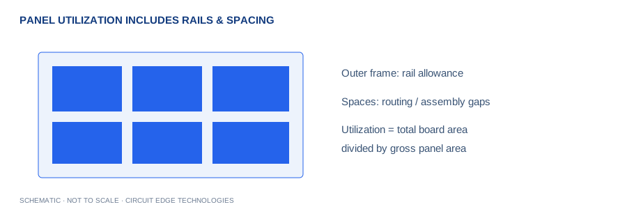
Rails consume space on every edge. This calculator subtracts twice the rail width from both panel dimensions before placing boards. Utilization is measured against the full gross rectangular panel, including rails and inter-board spacing. This definition makes comparisons explicit; a supplier quoting utilization against only the usable area can report a different percentage for the same physical arrangement.
Compare uniform orientations
The algorithm evaluates a uniform grid with the original board width and height, then another grid with every board rotated by ninety degrees. It selects the larger count. It does not search mixed orientations, staggered arrangements or irregular nesting. A specialist panel designer may find a better arrangement, particularly when board dimensions and leftover strips permit combinations that a uniform grid cannot use.
Reserve manufacturing and assembly space
Spacing is the gap between neighboring board outlines. Routing tool diameter, tabs, mouse bites, V-score limits and component overhang can all impose additional restrictions. Rails may need fiducials, tooling holes, barcodes or conveyor support. Components close to the edge can conflict after rotation or depanelization. Discuss panel handling with both fabrication and assembly partners before treating the geometric count as a production quotation.
Use the result to guide a quotation
Compare nearby standard panel sizes while holding board geometry and rail assumptions fixed. A small outline change can occasionally add a complete row, but changing a product enclosure solely for panel yield may not be worthwhile. Consider finished-board yield, testing access and depanelization damage alongside area utilization. Provide an assembly drawing and ask which panel dimensions correspond to the actual quoted manufacturing process rather than optimizing an arbitrary rectangle.
Work from your project brief
Start by confirming the units shown beside each input. Enter the operating condition you expect in the finished product, then change one variable at a time so the effect stays clear. The plus and minus controls make small adjustments, while the slider is useful for a quick sensitivity sweep. Blank fields, impossible ranges and unsupported geometries stop the calculation instead of silently preserving a previous result. A unit change converts the displayed value while the underlying calculation keeps a consistent canonical unit system.
Keep a Circuit Edge board-review record
Use Copy Results for a design-review note, CSV for a calculation register, and Share Link to preserve the input values in the URL. Download PDF creates a local report with the inputs, outputs, formula and limitations. The exported estimate is only useful when its assumptions remain attached. Keep the board revision, stackup revision, supplier tolerances and applicable load or interface requirement in the same review record. A later fabrication change can invalidate an earlier calculation even if the calculator inputs have not changed.
Separate the displayed digits from project confidence
Several digits are displayed to make comparisons and unit conversions useful. Those digits do not imply matching physical accuracy. Manufacturing variation, environmental conditions and the simplicity of the selected model can dominate the final result. Round the chosen design requirement in a direction that preserves engineering margin, then agree the tolerance with your fabricator. Use prototype measurements and the relevant analysis tools when a small change would affect reliability, regulatory compliance or product performance.
Worked example
40 × 30 mm boards on a 250 × 200 mm panel with 10 mm rails and 2 mm spacing fit 28 boards in the rotated uniform grid, using 67.2% of gross panel area. Use the defaults as a reproducible starting point, then substitute your own board data. When comparing a manual calculation, keep dimensional units consistent and avoid rounding intermediate values. If your result differs, check the input definitions before changing the model or applying an unexplained correction factor.
Continue with our calculation methodology, fabrication review checklist and high-speed layout guide. For board-specific support, contact Circuit Edge Technologies.
Frequently asked questions
What does the panelization tool calculate?
Prepare a supplier panel discussion with board dimensions, rails and gaps, then compare two uniform orientations. Tests two uniform rectangular orientations, not mixed-orientation packing. Fabricator tooling, V-score restrictions, tabs, fiducials and assembly clearances can reduce the usable count.
Which formula does this calculator use?
Nx = floor[(panel_width−2rail+spacing)/(board_width+spacing)], similarly Ny. Count = NxNy; utilization = count × board area / gross panel area. The Methodology page records the model and its limitations so that a design reviewer can reproduce the assumptions.
How should I check the input definitions?
Rails consume space on every edge. This calculator subtracts twice the rail width from both panel dimensions before placing boards. Utilization is measured against the full gross rectangular panel, including rails and inter-board spacing. This definition makes comparisons explicit; a supplier quoting utilization against only the usable area can report a different percentage for the same physical arrangement.
What is a useful worked example?
40 × 30 mm boards on a 250 × 200 mm panel with 10 mm rails and 2 mm spacing fit 28 boards in the rotated uniform grid, using 67.2% of gross panel area. This example is a starting point for checking units, not a universal production recommendation.
Can I use the result as a fabrication or compliance approval?
Tests two uniform rectangular orientations, not mixed-orientation packing. Fabricator tooling, V-score restrictions, tabs, fiducials and assembly clearances can reduce the usable count. Obtain the required engineering and manufacturing review before releasing a critical design.
How can I save and share my calculation?
Copy Results includes the inputs, outputs and limitations. CSV provides a local record, while Download PDF creates a local engineering report. Share Link encodes the canonical input values in the URL. Anyone with the link can reproduce that input set.
What should I verify before design release?
Compare nearby standard panel sizes while holding board geometry and rail assumptions fixed. A small outline change can occasionally add a complete row, but changing a product enclosure solely for panel yield may not be worthwhile. Consider finished-board yield, testing access and depanelization damage alongside area utilization. Provide an assembly drawing and ask which panel dimensions correspond to the actual quoted manufacturing process rather than optimizing an arbitrary rectangle.
Inputs and related calculators
Board width, Board height, Panel width, Panel height, Rail on each edge, Board-to-board spacing.