
PCB Via Current Calculator
Examine a layer transition before the PCB release: barrel geometry, array resistance and the limits of a shared-current assumption.
Design inputs
01 / CONFIGURECalculation workspace
02 / EXPLOREMapping the trace power law to barrel area is a heuristic, not a validated IPC via rating. Linear current scaling assumes identical, equally fed vias; mutual heating and unequal sharing are omitted. Results are estimates; confirm critical designs with your fabricator.
How it works · formula & assumptions
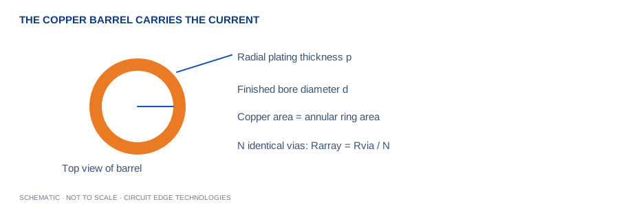
A = π[(d/2+p)² − (d/2)²]; R = ρL/A; array R = R/N. Screening I = N × 0.024 × ΔT^0.44 × A_mil²^0.725.
Mapping the trace power law to barrel area is a heuristic, not a validated IPC via rating. Linear current scaling assumes identical, equally fed vias; mutual heating and unequal sharing are omitted.
What changes when the supply moves between layers?
What changes when the supply moves between layers?
A wide external pour may feed a small bank of plated barrels. Describe the finished bore, minimum barrel plating and connected layers before comparing current paths. Via count is useful only when the copper can distribute current to that count.
Review the incoming and outgoing copper together
The Circuit Edge transition review should show pad exits, internal-plane connections and the feed geometry on each layer. Request minimum barrel plating from the supplier. Use the array result as a screening comparison and validate current sharing and temperature on the assembled board.
The question this Circuit Edge workspace addresses
Examine a layer transition before the PCB release: barrel geometry, array resistance and the limits of a shared-current assumption. Mapping the trace power law to barrel area is a heuristic, not a validated IPC via rating. Linear current scaling assumes identical, equally fed vias; mutual heating and unequal sharing are omitted.
Formula and assumptions
A = π[(d/2+p)² − (d/2)²]; R = ρL/A; array R = R/N. Screening I = N × 0.024 × ΔT^0.44 × A_mil²^0.725.
Understand the barrel area
The finished hole is the empty bore after plating. Copper occupies a ring around that bore; its cross-section is not the circular hole area. The calculator uses finished hole diameter and radial wall plating to compute the copper annulus. If your fabricator supplies drill diameter instead, obtain the finished-hole target before using this model. Plating thickness on an outer surface is not necessarily the same as the guaranteed minimum inside the hole.
Use a parallel array carefully
The array estimate multiplies a single-barrel screening current by the number of vias and divides its electrical resistance by that number. This assumes equal geometry and equal feeding resistance. A row fed from one end can concentrate current in the nearest barrels. Shared copper regions also couple the thermal behavior. Increasing via count is useful, but the displayed linear scaling should be treated as an optimistic electrical-sharing assumption rather than a measured temperature guarantee.
Separate electrical and thermal roles
A power via carries load current between layers; a thermal via may primarily transport heat. Both rely on copper, but their design objectives differ. This tool estimates DC barrel resistance and a heuristic current baseline. It does not model heat spreading from a component, solder-filled barrels, via-in-pad processing or junction temperature. Consider plugged or capped constructions with the fabricator before using a via under an exposed solder pad.
Review fabrication and layout together
Specify minimum barrel plating, aspect ratio and reliability requirements in the fabrication package. Use short, broad feed regions on every connected layer. Check pad and antipad geometry so nearby clearances do not create a bottleneck. Compare the via array with the trace feeding it and inspect the return connection. On a prototype, measure temperature near the transition under continuous load and verify that connector or pad resistance is not dominating the result.
Work from your project brief
Start by confirming the units shown beside each input. Enter the operating condition you expect in the finished product, then change one variable at a time so the effect stays clear. The plus and minus controls make small adjustments, while the slider is useful for a quick sensitivity sweep. Blank fields, impossible ranges and unsupported geometries stop the calculation instead of silently preserving a previous result. A unit change converts the displayed value while the underlying calculation keeps a consistent canonical unit system.
Keep a Circuit Edge board-review record
Use Copy Results for a design-review note, CSV for a calculation register, and Share Link to preserve the input values in the URL. Download PDF creates a local report with the inputs, outputs, formula and limitations. The exported estimate is only useful when its assumptions remain attached. Keep the board revision, stackup revision, supplier tolerances and applicable load or interface requirement in the same review record. A later fabrication change can invalidate an earlier calculation even if the calculator inputs have not changed.
Separate the displayed digits from project confidence
Several digits are displayed to make comparisons and unit conversions useful. Those digits do not imply matching physical accuracy. Manufacturing variation, environmental conditions and the simplicity of the selected model can dominate the final result. Round the chosen design requirement in a direction that preserves engineering margin, then agree the tolerance with your fabricator. Use prototype measurements and the relevant analysis tools when a small change would affect reliability, regulatory compliance or product performance.
Worked example
A 0.30 mm finished hole with 25 µm radial plating contains about 0.0255 mm² of barrel copper. Two identical 1.6 mm barrels have about 0.54 mΩ resistance at 20 °C. Use the defaults as a reproducible starting point, then substitute your own board data. When comparing a manual calculation, keep dimensional units consistent and avoid rounding intermediate values. If your result differs, check the input definitions before changing the model or applying an unexplained correction factor.
Continue with our calculation methodology, fabrication review checklist and high-speed layout guide. For board-specific support, contact Circuit Edge Technologies.
Frequently asked questions
What does the via current tool calculate?
Examine a layer transition before the PCB release: barrel geometry, array resistance and the limits of a shared-current assumption. Mapping the trace power law to barrel area is a heuristic, not a validated IPC via rating. Linear current scaling assumes identical, equally fed vias; mutual heating and unequal sharing are omitted.
Which formula does this calculator use?
A = π[(d/2+p)² − (d/2)²]; R = ρL/A; array R = R/N. Screening I = N × 0.024 × ΔT^0.44 × A_mil²^0.725. The Methodology page records the model and its limitations so that a design reviewer can reproduce the assumptions.
How should I check the input definitions?
The finished hole is the empty bore after plating. Copper occupies a ring around that bore; its cross-section is not the circular hole area. The calculator uses finished hole diameter and radial wall plating to compute the copper annulus. If your fabricator supplies drill diameter instead, obtain the finished-hole target before using this model. Plating thickness on an outer surface is not necessarily the same as the guaranteed minimum inside the hole.
What is a useful worked example?
A 0.30 mm finished hole with 25 µm radial plating contains about 0.0255 mm² of barrel copper. Two identical 1.6 mm barrels have about 0.54 mΩ resistance at 20 °C. This example is a starting point for checking units, not a universal production recommendation.
Can I use the result as a fabrication or compliance approval?
Mapping the trace power law to barrel area is a heuristic, not a validated IPC via rating. Linear current scaling assumes identical, equally fed vias; mutual heating and unequal sharing are omitted. Obtain the required engineering and manufacturing review before releasing a critical design.
How can I save and share my calculation?
Copy Results includes the inputs, outputs and limitations. CSV provides a local record, while Download PDF creates a local engineering report. Share Link encodes the canonical input values in the URL. Anyone with the link can reproduce that input set.
What should I verify before design release?
Specify minimum barrel plating, aspect ratio and reliability requirements in the fabrication package. Use short, broad feed regions on every connected layer. Check pad and antipad geometry so nearby clearances do not create a bottleneck. Compare the via array with the trace feeding it and inspect the return connection. On a prototype, measure temperature near the transition under continuous load and verify that connector or pad resistance is not dominating the result.
Inputs and related calculators
Finished hole diameter, Barrel plating thickness, Parallel vias, Temperature rise, Conductor length, Ambient temperature.