
0.5 mm Via Current Estimate for Six Vias
Examine a layer transition before the PCB release: barrel geometry, array resistance and the limits of a shared-current assumption.
0.5 mm Via Current Estimate for Six Vias
This preset explores six 0.50 mm finished holes with the same nominal plating and board thickness as the smaller cases. The resulting low DC resistance may be useful for comparing alternatives, but it does not prove a maximum safe array current. Plane spreading resistance, solder joints and terminal interfaces can dominate the complete connection. Use the output to document geometry, then review the current path through the whole board.
Design inputs
01 / CONFIGURECalculation workspace
02 / EXPLOREMapping the trace power law to barrel area is a heuristic, not a validated IPC via rating. Linear current scaling assumes identical, equally fed vias; mutual heating and unequal sharing are omitted. Results are estimates; confirm critical designs with your fabricator.
How it works · formula & assumptions
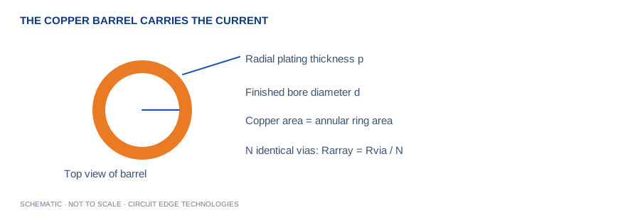
A = π[(d/2+p)² − (d/2)²]; R = ρL/A; array R = R/N. Screening I = N × 0.024 × ΔT^0.44 × A_mil²^0.725.
Mapping the trace power law to barrel area is a heuristic, not a validated IPC via rating. Linear current scaling assumes identical, equally fed vias; mutual heating and unequal sharing are omitted.
A larger via bank for power distribution
This preset explores six 0.50 mm finished holes with the same nominal plating and board thickness as the smaller cases. The resulting low DC resistance may be useful for comparing alternatives, but it does not prove a maximum safe array current. Plane spreading resistance, solder joints and terminal interfaces can dominate the complete connection. Use the output to document geometry, then review the current path through the whole board.
Review priorities for this case
Check whether the array obstructs return routing or creates a line of antipads in a reference plane. A large via bank can solve a power problem while damaging signal return continuity. Use thermography or appropriate temperature sensors during prototype validation and confirm the barrel reliability requirements with the supplier.
Model and limits
A = π[(d/2+p)² − (d/2)²]; R = ρL/A; array R = R/N. Screening I = N × 0.024 × ΔT^0.44 × A_mil²^0.725.
Mapping the trace power law to barrel area is a heuristic, not a validated IPC via rating. Linear current scaling assumes identical, equally fed vias; mutual heating and unequal sharing are omitted.
Compare before committing
Change one assumption at a time and save the resulting input set with the board revision. Compare the estimate with the full tool explanation, then check local bottlenecks and manufacturing tolerances. These case values describe one starting scenario; they do not replace the product requirements or the fabricator stackup.
Continue with our calculation methodology, fabrication review checklist and high-speed layout guide. For board-specific support, contact Circuit Edge Technologies.
Frequently asked questions
What does the via current tool calculate?
Examine a layer transition before the PCB release: barrel geometry, array resistance and the limits of a shared-current assumption. Mapping the trace power law to barrel area is a heuristic, not a validated IPC via rating. Linear current scaling assumes identical, equally fed vias; mutual heating and unequal sharing are omitted.
Which formula does this calculator use?
A = π[(d/2+p)² − (d/2)²]; R = ρL/A; array R = R/N. Screening I = N × 0.024 × ΔT^0.44 × A_mil²^0.725. The Methodology page records the model and its limitations so that a design reviewer can reproduce the assumptions.
How should I check the input definitions?
The finished hole is the empty bore after plating. Copper occupies a ring around that bore; its cross-section is not the circular hole area. The calculator uses finished hole diameter and radial wall plating to compute the copper annulus. If your fabricator supplies drill diameter instead, obtain the finished-hole target before using this model. Plating thickness on an outer surface is not necessarily the same as the guaranteed minimum inside the hole.
What is a useful worked example?
A 0.30 mm finished hole with 25 µm radial plating contains about 0.0255 mm² of barrel copper. Two identical 1.6 mm barrels have about 0.54 mΩ resistance at 20 °C. This example is a starting point for checking units, not a universal production recommendation.
Can I use the result as a fabrication or compliance approval?
Mapping the trace power law to barrel area is a heuristic, not a validated IPC via rating. Linear current scaling assumes identical, equally fed vias; mutual heating and unequal sharing are omitted. Obtain the required engineering and manufacturing review before releasing a critical design.
How can I save and share my calculation?
Copy Results includes the inputs, outputs and limitations. CSV provides a local record, while Download PDF creates a local engineering report. Share Link encodes the canonical input values in the URL. Anyone with the link can reproduce that input set.
What should I verify before design release?
Specify minimum barrel plating, aspect ratio and reliability requirements in the fabrication package. Use short, broad feed regions on every connected layer. Check pad and antipad geometry so nearby clearances do not create a bottleneck. Compare the via array with the trace feeding it and inspect the return connection. On a prototype, measure temperature near the transition under continuous load and verify that connector or pad resistance is not dominating the result.